DIY PCB like Caveman?
JLCPCB sends a small free gift with your order. Sometimes it's a leaky pen or a very short ruler. This week it was a roll of tape with a hilarious cartoon on the front:
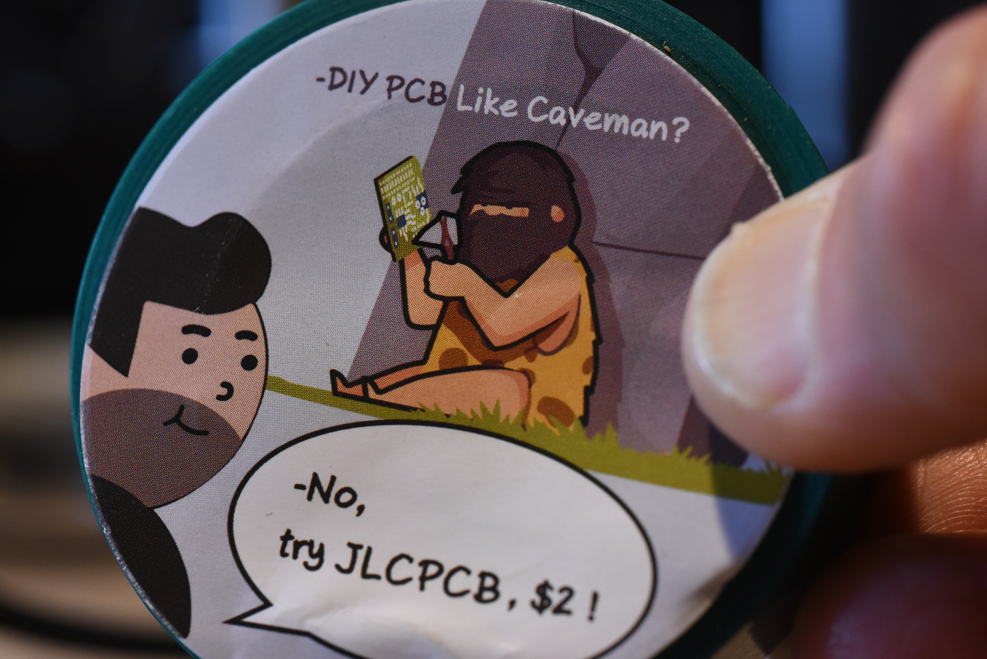
By a small coincidence this weekend I really did make my own PCB -- for the first time in 20 years. Here is how that happened.
On Friday we assembled the first "final" Gameduino Dazzler modules. These are very close to what's going to be manufactured.
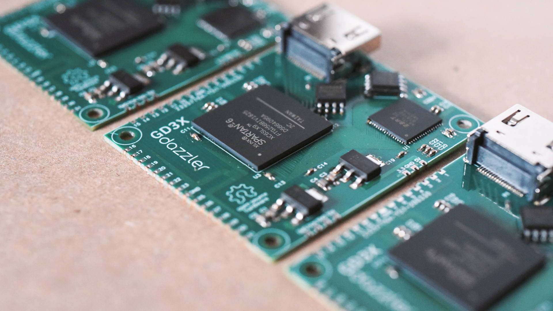
To test them, there needs to be a fixture to hold the board in place and connect to its pads. This is the same fixture that will be used at manufacturing time. So I cut one out of acrylic, using metric standoffs. This is the technique that worked for the SPIDriver and I²CDriver fixtures. It's quick and reliable.
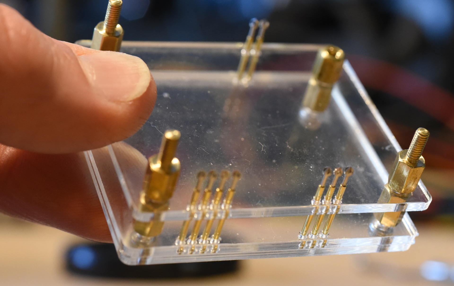
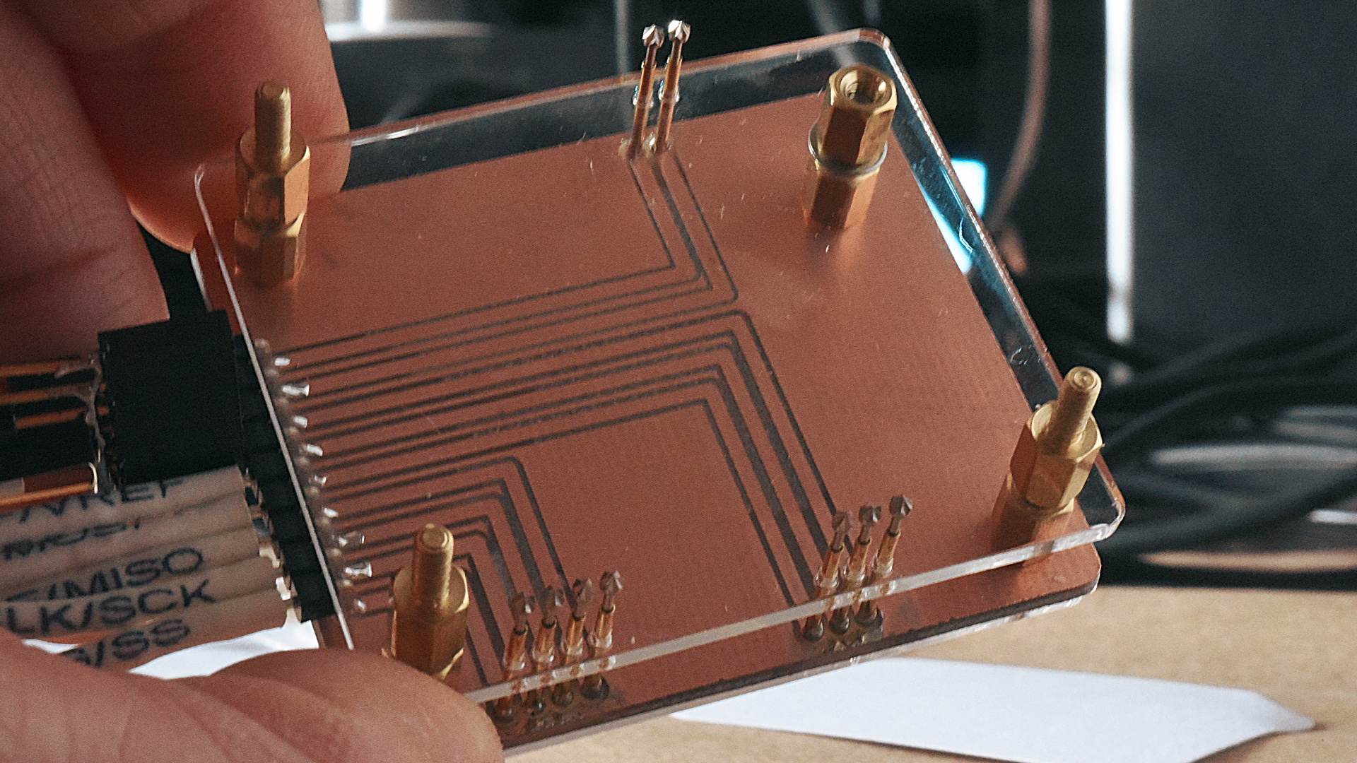
This one uses nine P75-LM2 pogo pins to connect to the terminals of the Dazzler. These power the board and expose the JTAG interface. The tester hardware (to be decided; likely another Dazzler) can load the onboard FPGA with an initial bitstream.
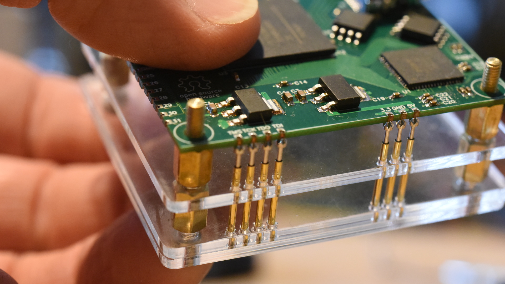
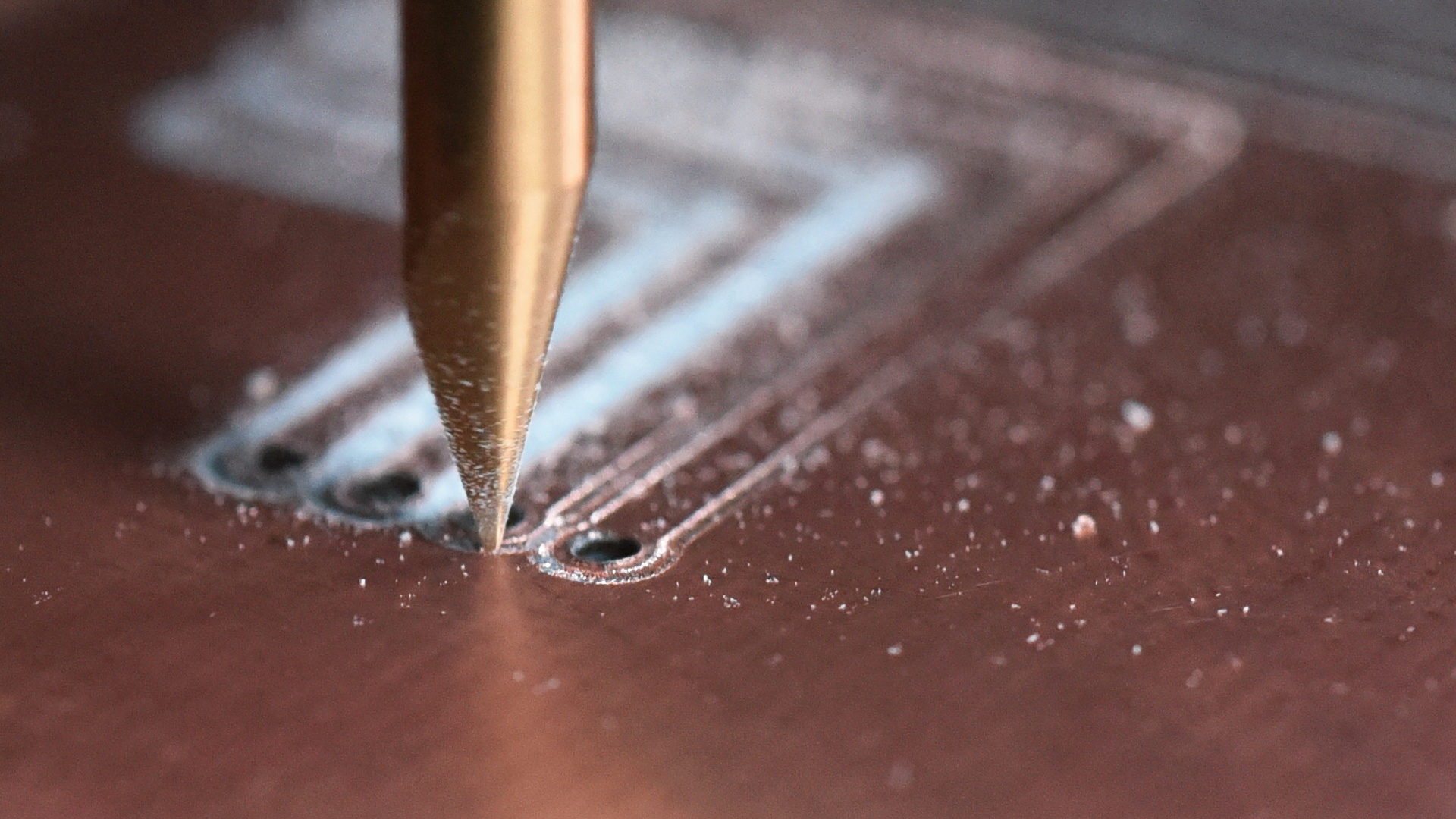
This was the moment when I hesitated. The next step was to hand-solder tiny wires to each pogo pin. But it never goes well. The result is always a fragile mess. But a PCB to route the signals would be simple and would work so much better! I'd bought the materials to make PCBs a couple of months ago -- this was the perfect opportunity to cut a PCB for the first time.
The ingredient list:
- A Taig CNC milling machine - details here
- Double-sided copper boards
- An engraving bit for cutting the tracks
- A set of fine end mills for the holes
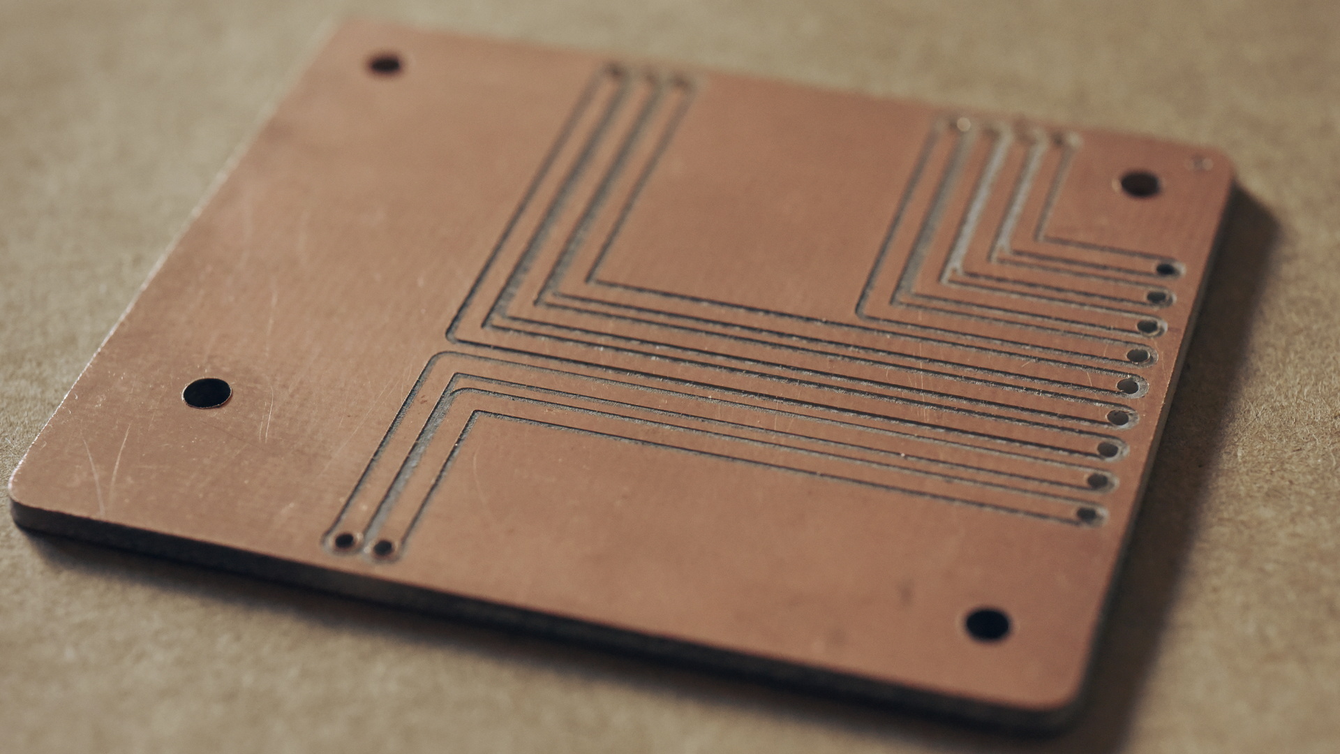
Here's the finished board, after cleaning up the rough outer edges with a needle file. It's a single-sided board and maybe took an hour total to design and cut.
The completed stack, with pins soldered into place:
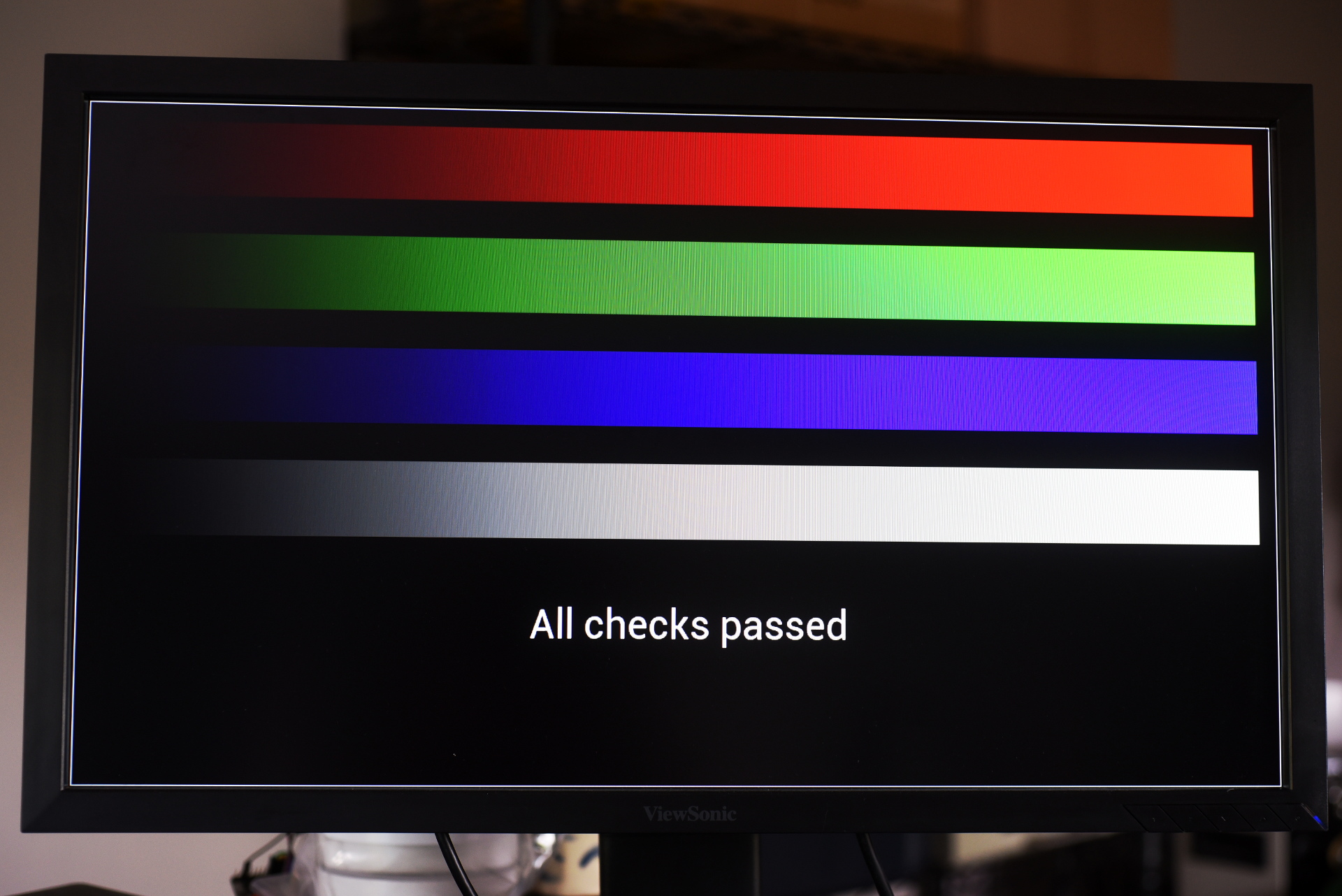
With it, the test program can be loaded onto the FPGA, and prove that the graphics to HDMI pipeline is alive, in glorious 24-bit color:
Thanks for reading. Next week Dazzler should pass a small but significant milestone... stay tuned.