How would Bob Ross lay out a PCB?
The late Bob Ross had a TV show in the 80s and 90s called "The Joy of Painting." Every 25 minute episode (there are hundreds) he would paint a landscape from scratch.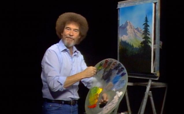
After you've watched a couple, you get to know the routine. It's always a landscape. He has a fixed palette of colors, and a fixed set of techniques for drawing the same elements again and again. Sky, mountains, snow, trees, lakes, ocean. For each of these he has worked out a brush and paint combination that lets him get a consistent result in a minimum of time. If you're wondering how he paints a bicycle, the answer is that he doesn't. He only puts things in his paintings that he can do easily. So... no bicycles, but plenty of snow-capped mountains and pine trees.
Bob quite often mentions how he used to be a "traditional" painter, before he started using these time-saving techniques. He'll talk about the hours he used to spend on clouds. He uses a fan brush to make fluffy edged clouds in mere seconds. The traditional way took hours or days, he explains, as he finishes the painting in minutes.
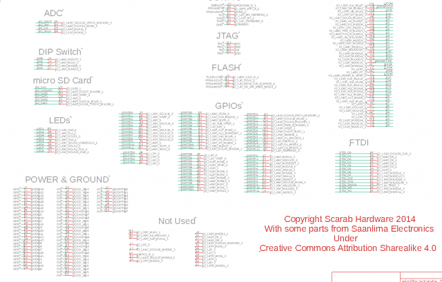
Here's what PCB layout is like using a traditional tool. First you make a schematic -- a map of the circuit. For modern digital designs this is often a giant list of signal-to-signal connections like this. It's not really a map at all, more like a list.
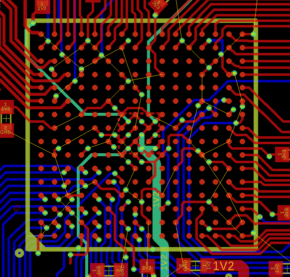
Then you place the components on the board, and wire them up. After you've started to wire them up, you might decide to move them around. In this case you rip up the connecting wires, move the parts, and start again. Repeat until the circuit is completely laid out.
What's a more Bob Ross way of doing this? Here's some speculation.
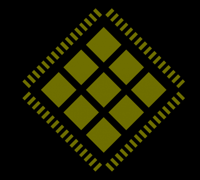
He'd have a library of parts, of course. Here's a QFN 64 footprint.
The traditional tools have part libraries too, but Bob might go a little further by also having a library of escapes.
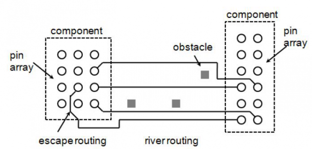
The escape is getting the signals away from the part pins. The river is a collection of parallel signals that can all be routed together.
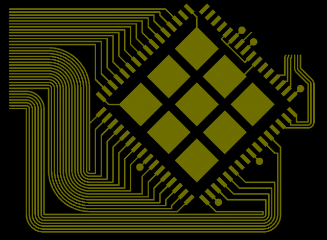
So instead of just having the footprint for a part, why not include the escape pattern in with it? That way you're all set to start river routing. Here's a BT815 with all power pins hooked up and all external signals routed into two rivers. The 35-signal river on the left contains all the external connections. The 6-signal river on the right is the BT815's private flash interface.
Add the SOIC8 flash, and its escape. (Just as Bob Ross has prepared the ideal brush for the job, here the SOIC8's escape is cunningly arranged to get the signals into the right correct order to match the BT815).
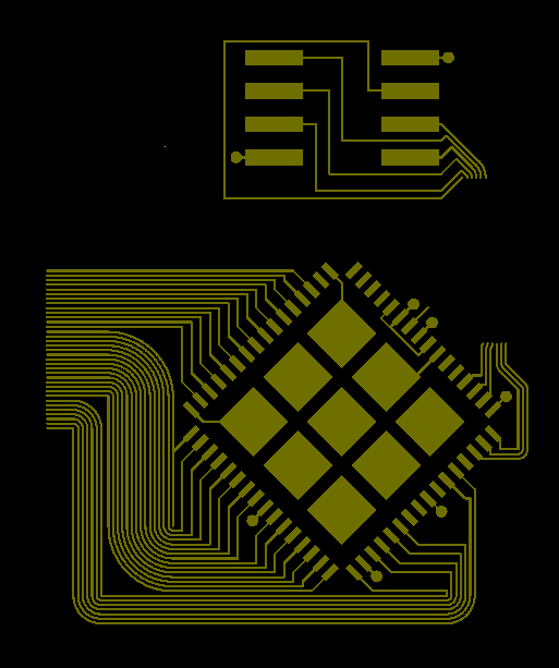
It's now trivial to connect the two rivers:
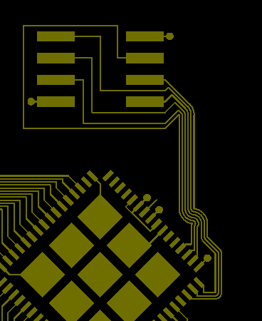
Viola, the BT815 and its flash are hooked up. And these same primitive elements -- escapes; river turns, splits, and joins -- can be used repeatedly to hook up the entire board. Like painting the Bob Ross way, having a small set of techniques guides your thinking, drastically speeding up the process.
Thanks for reading. The PCB I'm working on here is the Gameduino 3X HDMI, I'll post more of it as it progresses.